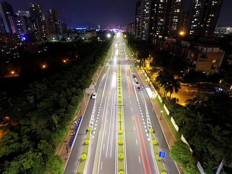
Design Requirements For LED Street Lights
1. The biggest feature of lighting LEDs is the function of directional light emission, because almost all power LEDs are equipped with reflectors, and the efficiency of such reflectors is significantly higher than that of lamps. In addition, the efficiency of the self-reflector has been included in the detection of the light effect of the LED. Road luminaires using LEDs should make full use of the directional emission characteristics of LEDs, so that each LED in the road luminaires directly emit light to each area of the illuminated road surface, and then use the auxiliary light distribution of the luminaire reflector to achieve Very reasonable comprehensive light distribution of road lamps. It should be said that road lamps must truly meet the illuminance and uniformity requirements of CJJ45-2006 and CIE31 and CIE115 standards, and the three-time light distribution function in the luminaire can be better realized. And the LED with a reflector and a reasonable beam output angle itself has a good primary light distribution function. In the luminaire, the installation position and emission direction of each LED can be designed according to the height of the street luminaire and the width of the road surface to achieve a good secondary light distribution function. The reflector in this type of lamps is only used as an auxiliary three-time light distribution method to ensure a better uniformity of road illumination.
In the design of actual road lighting fixtures, each LED can be fixed on the fixture with a spherical universal joint under the premise of basically setting the lighting direction of each LED. When the fixture is used in different heights and illumination widths At the same time, the spherical universal joint can be adjusted so that the illumination direction of each LED achieves a satisfactory result. When determining the power and beam output angle of each LED, according to E(lx)=I(cd)/D(m)2 (light intensity and illuminance distance inverse square law), the basic selection of each LED can be calculated The power that the beam output angle should have, and the light output of each LED can reach the expected value by adjusting the power of each LED and the different power output from the LED drive circuit to each LED. These adjustment methods are peculiar to road lamps using LED light sources, and making full use of these features can reduce the lighting power density under the premise of meeting the road surface illuminance and uniformity of illuminance, and achieve the purpose of energy saving.
2. The power system of LED street lights is also different from traditional light sources. The constant current drive power required by LEDs is a cornerstone to ensure its normal operation. Simple switching power supply solutions often bring damage to LED devices. How to make a group of LEDs tightly packed together is also an indicator for investigating LED street lights. The requirement of the LED on the drive circuit is to ensure the characteristics of constant current output. Because the junction voltage is relatively small when the LED is working in the forward direction, the constant LED drive current is guaranteed to basically ensure the constant output power of the LED. For the current situation of unstable power supply voltage in our country, it is very necessary for the driving circuit of the road lamp LED to have a constant current output characteristic, which can ensure the constant light output and prevent the LED from overpowering.
In order to make the LED drive circuit exhibit constant current characteristics, looking inward from the output end of the drive circuit, its output internal impedance must be high. When working, the load current also passes through this output internal impedance. If the drive circuit is composed of a step-down, rectification and filtering followed by a DC constant current source circuit or a general switching power supply plus a resistance circuit, it must also consume a lot of active power. Therefore, the efficiency of these two types of drive circuits is unlikely to be high under the premise of basically satisfying the constant current output. The correct design scheme is to use active electronic switching circuit or high-frequency current to drive the LED. Using the above two schemes can make the drive circuit have a high conversion efficiency under the premise of maintaining good constant current output characteristics.
The road lamps and lanterns in our country basically adopt the mode of HID light source plus trigger and inductive ballast, although this mode has the problem of low energy efficiency and stroboscopic. An important aspect that threatens the plasticity of LED lamps with electronic drive circuits when used in outdoor lighting situations is the lightning induction problem.
As we all know, lightning in the sky emits a broad-spectrum radio wave, while the power supply lines for overhead road lamps are well-received wireless. The radio waves emitted by the same lightning received by the two power lines are common mode interference signals for the drive circuit. This common mode interference can reach hundreds of volts to thousands of volts to the ground, and it is easy to break down in the drive circuit. EMC grounding capacitance or a small electrical gap to the ground (to the shell) can cause damage to the drive circuit.
In addition, since my country’s power supply line is a three-phase four-wire neutral line grounded polar power supply, in each section of the two overhead power supply lines, at the moment when the radio wave of lightning is induced, the two power supply lines are connected to the ground. The instantaneous impedance is different and a differential mode interference voltage is generated between the two power supply lines. This instantaneous differential mode interference voltage can also reach hundreds of volts to more than 3000 volts. This voltage often breaks down the power rectifier diode and printed circuit of the drive circuit. To control the electrical gap between the electrodes of different polarities on the circuit board, the LED controller will also damage the drive circuit.
To solve this problem, a fast-response varistor must be connected to the input end of the LED drive circuit to ensure the discharge of differential mode interference. Since the inductive interference of lightning is repeated many times, when the interference voltage is high, the instantaneous conduction and discharge current of the varistor may be large. Therefore, the varistor used should not only have a fast response capability, but also have an instantaneous conduction. The discharge capacity of dozens of amperes is not damaged. In addition to the use of varistors, the input end of the LED drive circuit should also be combined with conducted interference (EMI) protection, and a composite LC network should be designed so that these LC networks can not only prevent internal EMI from leaking to the grid, but also The interference signal of lightning has an obvious inhibitory effect.
In addition, the electrical clearance between each point of the LED drive circuit and the ground should be kept above 7mm. The grounding capacitance of EMI protection and the ground insulation strength of the drive circuit should meet the requirements of reinforced insulation (4V+2750V), which can make the LED The drive circuit has good resistance to differential mode and common mode lightning induction.


